Aloft Forums
You are using an out of date browser. It may not display this or other websites correctly.
You should upgrade or use an alternative browser.
You should upgrade or use an alternative browser.
Thor.2 --- Slopesoarer with F3f/b genes
- Thread starter vanquish
- Start date
vanquish
Active User
Hello,
First of all, I would like to apologize for the delay in my new post. Before Christmas, there was a lot of work to be done in the office/job and I deliberately wanted to switch off and spend the Christmas holidays with my family in peace. But now it's starting again.
Finding a good sparring partner for the outer airfoil has proven to be very difficult. It should be a well-known airfoil with comparable thickness and camber and designed for a similar purpose. In the end, I ended up with the good old MH30 from Martin Hepperle. This airfoil is very suitable for small and fast slope gliders up to about 2.0m wingspan. In the mid/late 90s, a large number of F5b class models were profiled with the MH30 because it was simply a force in high-speed flight. It is slightly thinner than my THOR.2 design; the camber is almost identical... About 10 years ago, Philip Kolb published a profile strake for medium-sized slope and aerobatic models based on the MH30. Due to his fame, the similar “hard facts” and the public availability, it seems to me to be a good choice for a airfoil comparison.
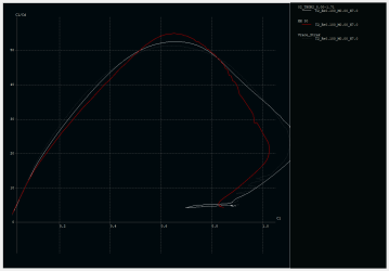
The following picture shows the MH30 and the Thor.2 outer profile in comparison. The equivalent Vrace profile is also included again. In the area of the main wing with a class-typical chord length, we are in the range of Re100k – Re400k, depending on the flight speed. Whereby Re400k is already very fast...
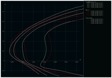
A similar design philosophy can certainly be seen here. The THOR.2 has a clear advantage here, although its lead decreases as the Re numbers increase.
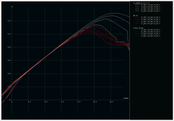
Like the base, the THOR.2 outer profile is at its strongest in EM-style turns. The MH30 is on a comparable level. However, Martin Hepperle's design is clearly at a disadvantage in tight turns. At this point, even the Vrace has a strong opponent in the THOR.2.
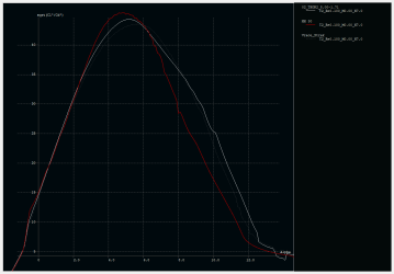
Finally, here too is the glide polar (type 2 – constant lift). Here, the MH30 is slightly ahead at the maximum rate of climb. When gliding in the slope flight typical range, the THOR.2 is again ahead.
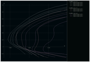
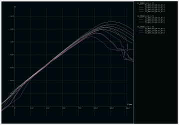
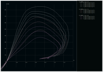
There is another Re-number-adapted profile at the very outer wing. Basically, it is “only” the profile presented here, slightly thinned out and with a stronger thickness overlay. Finally you can see the entire profile strake of the THOR.2 wing.
FLZ-Vortex
I use a small program called FLZ-Vortex to simulate the wing. This tool is very good at simulating the stall behavior in a surprisingly realistic way. In the following picture, you can see how the stall announces itself on the THOR.2 wing.
The green dashed line represents the lift that the profile can provide. The solid green line shows the actual lift coefficient. If this is now above what the profile can deliver, the flow breaks away (stall). Shown here as a red area. In this simulation, the very outside wing tip should be treated with caution. At such small Re numbers/wing depths, these simulations fail. The middle area of the wing is more exciting:

Here you can clearly see that the stall begins in the middle of the entire wing and expands outwards with increasing lift. This causes the aircraft to feel rather spongy or soft at first, or ideally it simply sags. This is exactly what we want to achieve for a gentle stall behavior.
If the stall were to occur first on the outer wing, the model would most likely tip over to one side...
As mentioned at the beginning, I didn't want to design an ultra-thin wing with the THOR.2. Thin profiles may feel light and agile and, in the Re number range relevant to this model, they also have good drag coefficients, but in my experience they also need more attention in flight and certainly during construction. When it comes to getting torsion under control in the wing, it takes either height or (high-quality) material. The latter costs more to buy and ultimately drives up the model price. I would like to mitigate this by using height/thickness. 8.14-8.00-7.54% are not exactly thick profiles either, but I think they are a good compromise.
So, that was the layout of the wing roughly explained.
Next up is the tail unit (only very briefly) and the fuselage design. Jerry and his team have also been very busy. Shortly before Christmas, I received a photo of the first finished model. I can't wait to finally hold the first two models in my hands!
Kind regards,
Mario
First of all, I would like to apologize for the delay in my new post. Before Christmas, there was a lot of work to be done in the office/job and I deliberately wanted to switch off and spend the Christmas holidays with my family in peace. But now it's starting again.
Finding a good sparring partner for the outer airfoil has proven to be very difficult. It should be a well-known airfoil with comparable thickness and camber and designed for a similar purpose. In the end, I ended up with the good old MH30 from Martin Hepperle. This airfoil is very suitable for small and fast slope gliders up to about 2.0m wingspan. In the mid/late 90s, a large number of F5b class models were profiled with the MH30 because it was simply a force in high-speed flight. It is slightly thinner than my THOR.2 design; the camber is almost identical... About 10 years ago, Philip Kolb published a profile strake for medium-sized slope and aerobatic models based on the MH30. Due to his fame, the similar “hard facts” and the public availability, it seems to me to be a good choice for a airfoil comparison.
The following picture shows the MH30 and the Thor.2 outer profile in comparison. The equivalent Vrace profile is also included again. In the area of the main wing with a class-typical chord length, we are in the range of Re100k – Re400k, depending on the flight speed. Whereby Re400k is already very fast...

A similar design philosophy can certainly be seen here. The THOR.2 has a clear advantage here, although its lead decreases as the Re numbers increase.

Like the base, the THOR.2 outer profile is at its strongest in EM-style turns. The MH30 is on a comparable level. However, Martin Hepperle's design is clearly at a disadvantage in tight turns. At this point, even the Vrace has a strong opponent in the THOR.2.
Finally, here too is the glide polar (type 2 – constant lift). Here, the MH30 is slightly ahead at the maximum rate of climb. When gliding in the slope flight typical range, the THOR.2 is again ahead.


There is another Re-number-adapted profile at the very outer wing. Basically, it is “only” the profile presented here, slightly thinned out and with a stronger thickness overlay. Finally you can see the entire profile strake of the THOR.2 wing.


FLZ-Vortex
I use a small program called FLZ-Vortex to simulate the wing. This tool is very good at simulating the stall behavior in a surprisingly realistic way. In the following picture, you can see how the stall announces itself on the THOR.2 wing.
The green dashed line represents the lift that the profile can provide. The solid green line shows the actual lift coefficient. If this is now above what the profile can deliver, the flow breaks away (stall). Shown here as a red area. In this simulation, the very outside wing tip should be treated with caution. At such small Re numbers/wing depths, these simulations fail. The middle area of the wing is more exciting:
Here you can clearly see that the stall begins in the middle of the entire wing and expands outwards with increasing lift. This causes the aircraft to feel rather spongy or soft at first, or ideally it simply sags. This is exactly what we want to achieve for a gentle stall behavior.
If the stall were to occur first on the outer wing, the model would most likely tip over to one side...
As mentioned at the beginning, I didn't want to design an ultra-thin wing with the THOR.2. Thin profiles may feel light and agile and, in the Re number range relevant to this model, they also have good drag coefficients, but in my experience they also need more attention in flight and certainly during construction. When it comes to getting torsion under control in the wing, it takes either height or (high-quality) material. The latter costs more to buy and ultimately drives up the model price. I would like to mitigate this by using height/thickness. 8.14-8.00-7.54% are not exactly thick profiles either, but I think they are a good compromise.
So, that was the layout of the wing roughly explained.
Next up is the tail unit (only very briefly) and the fuselage design. Jerry and his team have also been very busy. Shortly before Christmas, I received a photo of the first finished model. I can't wait to finally hold the first two models in my hands!
Kind regards,
Mario
Doc J
Very Strong User
This is a road I know very well.Hello,
First of all, I would like to apologize for the delay in my new post. Before Christmas, there was a lot of work to be done in the office/job and I deliberately wanted to switch off and spend the Christmas holidays with my family in peace. But now it's starting again.
Finding a good sparring partner for the outer airfoil has proven to be very difficult. It should be a well-known airfoil with comparable thickness and camber and designed for a similar purpose. In the end, I ended up with the good old MH30 from Martin Hepperle. This airfoil is very suitable for small and fast slope gliders up to about 2.0m wingspan. In the mid/late 90s, a large number of F5b class models were profiled with the MH30 because it was simply a force in high-speed flight. It is slightly thinner than my THOR.2 design; the camber is almost identical... About 10 years ago, Philip Kolb published a profile strake for medium-sized slope and aerobatic models based on the MH30. Due to his fame, the similar “hard facts” and the public availability, it seems to me to be a good choice for a airfoil comparison.
The following picture shows the MH30 and the Thor.2 outer profile in comparison. The equivalent Vrace profile is also included again. In the area of the main wing with a class-typical chord length, we are in the range of Re100k – Re400k, depending on the flight speed. Whereby Re400k is already very fast...
View attachment 21640
A similar design philosophy can certainly be seen here. The THOR.2 has a clear advantage here, although its lead decreases as the Re numbers increase.
View attachment 21641
Like the base, the THOR.2 outer profile is at its strongest in EM-style turns. The MH30 is on a comparable level. However, Martin Hepperle's design is clearly at a disadvantage in tight turns. At this point, even the Vrace has a strong opponent in the THOR.2.
Finally, here too is the glide polar (type 2 – constant lift). Here, the MH30 is slightly ahead at the maximum rate of climb. When gliding in the slope flight typical range, the THOR.2 is again ahead.
View attachment 21642 View attachment 21643
There is another Re-number-adapted profile at the very outer wing. Basically, it is “only” the profile presented here, slightly thinned out and with a stronger thickness overlay. Finally you can see the entire profile strake of the THOR.2 wing.
View attachment 21644 View attachment 21645 View attachment 21646
FLZ-Vortex
I use a small program called FLZ-Vortex to simulate the wing. This tool is very good at simulating the stall behavior in a surprisingly realistic way. In the following picture, you can see how the stall announces itself on the THOR.2 wing.
The green dashed line represents the lift that the profile can provide. The solid green line shows the actual lift coefficient. If this is now above what the profile can deliver, the flow breaks away (stall). Shown here as a red area. In this simulation, the very outside wing tip should be treated with caution. At such small Re numbers/wing depths, these simulations fail. The middle area of the wing is more exciting:
View attachment 21647
Here you can clearly see that the stall begins in the middle of the entire wing and expands outwards with increasing lift. This causes the aircraft to feel rather spongy or soft at first, or ideally it simply sags. This is exactly what we want to achieve for a gentle stall behavior.
If the stall were to occur first on the outer wing, the model would most likely tip over to one side...
As mentioned at the beginning, I didn't want to design an ultra-thin wing with the THOR.2. Thin profiles may feel light and agile and, in the Re number range relevant to this model, they also have good drag coefficients, but in my experience they also need more attention in flight and certainly during construction. When it comes to getting torsion under control in the wing, it takes either height or (high-quality) material. The latter costs more to buy and ultimately drives up the model price. I would like to mitigate this by using height/thickness. 8.14-8.00-7.54% are not exactly thick profiles either, but I think they are a good compromise.
So, that was the layout of the wing roughly explained.
Next up is the tail unit (only very briefly) and the fuselage design. Jerry and his team have also been very busy. Shortly before Christmas, I received a photo of the first finished model. I can't wait to finally hold the first two models in my hands!
Kind regards,
Mario
It's looking nice, Mario.
Doc.
Mario - I'm very excited for you also!
It is amazing how many tools are available to aid in your design without major expense. Is it safe to say that you put no twist (washout) in your wings to control the stall? Just careful attention to the planform and airfoils gets your results?
It is amazing how many tools are available to aid in your design without major expense. Is it safe to say that you put no twist (washout) in your wings to control the stall? Just careful attention to the planform and airfoils gets your results?
vanquish
Active User
Personally, I wouldn't want to install a twist on a speed or all-round model. I see absolutely no need for it. But on a highly specialized thermal model, e.g. F3j or F5j, you can think about it. When circling tightly in the beard, perhaps only just above the ground, foolproof stall behavior is important. A moderate twist (see Prestige2 PK model) can certainly help here.
Doc J
Very Strong User
Planform is the secret.Yes, Wayne, correct! There is no twist in the wings. It‘s just taking an eye on the airfoil and planform… I do not like twist on speedwings.
At the moment I‘m working on a Pilatus B4 wing… maybe this will be the first time I need a twist
Doc.
Doc J
Very Strong User
That depends entirely on why the designer would even consider adding a twist to the wing in the first place. No designer ever does something unless there is a requirement or a perceived advantage - at least, I don't.Personally, I wouldn't want to install a twist on a speed or all-round model. I see absolutely no need for it. But on a highly specialized thermal model, e.g. F3j or F5j, you can think about it. When circling tightly in the beard, perhaps only just above the ground, foolproof stall behavior is important. A moderate twist (see Prestige2 PK model) can certainly help here.
If you start to look at how birds fly—especially fast birds—then graduate to ex-NASA aerodynamics Guru Doc Al. Bowers' Prandltl-inspired ESLD Vs BSLD studies. After a bit of consulting with the Good Doc and his helpers, you might start to integrate all this stuff with a few sums, and then wing twists could become really interesting.
I'm sure this is where the dissenters would cry, "Yeah, but Al Bowers used a flying wing, not a conventional wing tail setup!" But the reasons for that were really simple: A) a simple wing is easier and faster to make - and only the wing was of interest, and B) Al Bowers became influenced by the Horten experiments and just loved flying wings. Technically, the theory should work on any glider wing with a reasonable aspect ratio. It sure as hell works for birds.
If twisting the wing was purely for angular washout, I'd put the wing design back on the drawing board and start again. But if, as stated above, there might be a clear advantage...that is an entirely different scenario.
Doc.
Last edited:
vanquish
Active User
Well, designing a Horten-Wing cleanly is actually something else... The missing vertical tail must be compensated for by appropriate adjustments to the wing. Birds have a similar “problem”... But they also have fly-by-wire integrated as standard.
Fast birds are not necessarily fast in pure gliding flight. They are very fast in a nosedive (peregrine falcon, golden eagle), but here they have their wings largely laid out. The overall shape of the body is important here. Birds can also become fast in flapping flight. In this case, their wings not only fulfill the purpose of generating lift, but also propulsion. In pure gliding flight, a bird must fly mainly energy-efficiently. There is very interesting research into bird flight and we can still learn a great deal from nature...
There are applications for twisting, but I don't see them on speed or allround-oriented models with tail units.
Doc J
Very Strong User
Well, designing a Horten-Wing cleanly is actually something else... The missing vertical tail must be compensated for by appropriate adjustments to the wing. Birds have a similar “problem”... But they also have fly-by-wire integrated as standard.
Fast birds are not necessarily fast in pure gliding flight. They are very fast in a nosedive (peregrine falcon, golden eagle), but here they have their wings largely laid out. The overall shape of the body is important here. Birds can also become fast in flapping flight. In this case, their wings not only fulfill the purpose of generating lift, but also propulsion. In pure gliding flight, a bird must fly mainly energy-efficiently. There is very interesting research into bird flight and we can still learn a great deal from nature...
There are applications for twisting, but I don't see them on speed or allround-oriented models with tail units.
"There are applications for twisting, but I don't see them on speed or allround-oriented models with tail units."
Why not if they work?
Look at Aufwind's March/April "Gliding and Design" column for the next part of what we can learn from birds, or, for that matter, fish.
I have only been designing aircraft for 60 years - Birds have been doing it for 200 MILLION years. Maybe they got it right.
Doc.
Landru
Strong User
I saw a link to this thread in an email from Aloft and thought I'd pop in and take a look. 
The reference to wing twist was what caught my eye. From other reading, I remember that the NASA Prandtl-D flying project from a few years back claimed a significant reduction in induced drag, more than 10%, I believe.
One proposed real world application was for improved fuel economy in commercial aviation. I don't know if the concept has been acted on, but certainly wingtip devices are in widespread usage for the same reason -- and they could be considered a variant of the Prandtl approach. I suppose it would be better to say that the Prandtl bell-shaped span loading could be considered a more extensive implementation of the same principles. At least, these are the thoughts of some much more experienced aerodynacists than yours truly.
Ever since coming across the Prandtl project, I've wondered if there might benefits for a model glider model with a conventional tail. If someone's tried it, I haven't found any info on their results. The challenge of building a wing with a non-linear twist is definitely a bit off-putting. That said, there are a number of documented Prandtl-type models in existence, including a least one offered as a kit. I have one in progress at the moment.
I'll add a few links that I've enjoyed:

 www.amaflightschool.org
The reference to wing twist was what caught my eye. From other reading, I remember that the NASA Prandtl-D flying project from a few years back claimed a significant reduction in induced drag, more than 10%, I believe.
One proposed real world application was for improved fuel economy in commercial aviation. I don't know if the concept has been acted on, but certainly wingtip devices are in widespread usage for the same reason -- and they could be considered a variant of the Prandtl approach. I suppose it would be better to say that the Prandtl bell-shaped span loading could be considered a more extensive implementation of the same principles. At least, these are the thoughts of some much more experienced aerodynacists than yours truly.
Ever since coming across the Prandtl project, I've wondered if there might benefits for a model glider model with a conventional tail. If someone's tried it, I haven't found any info on their results. The challenge of building a wing with a non-linear twist is definitely a bit off-putting. That said, there are a number of documented Prandtl-type models in existence, including a least one offered as a kit. I have one in progress at the moment.
I'll add a few links that I've enjoyed:

Build NASA's PRANDTL Flying Wing | AMA Flight School
Explore the thrilling world of RC model flying with AMA Flight School. Dive into our rich collection of blogs, tips, and tutorials designed to elevate your flying skills. Whether you're a beginner or an experienced pilot, our expert advice answers all your 'How do I?' questions, guiding you...
US9382000B1 - Aircraft design - Google Patents
The present invention is an aircraft wing design that creates a bell shaped span load, which results in a negative induced drag (induced thrust) on the outer portion of the wing; such a design obviates the need for rudder control of an aircraft.
patents.google.com
Doc J
Very Strong User
Hi Andrew.I saw a link to this thread in an email from Aloft and thought I'd pop in and take a look.
The reference to wing twist was what caught my eye. From other reading, I remember that the NASA Prandtl-D flying project from a few years back claimed a significant reduction in induced drag, more than 10%, I believe.
One proposed real world application was for improved fuel economy in commercial aviation. I don't know if the concept has been acted on, but certainly wingtip devices are in widespread usage for the same reason -- and they could be considered a variant of the Prandtl approach. I suppose it would be better to say that the Prandtl bell-shaped span loading could be considered a more extensive implementation of the same principles. At least, these are the thoughts of some much more experienced aerodynacists than yours truly.
Ever since coming across the Prandtl project, I've wondered if there might benefits for a model glider model with a conventional tail. If someone's tried it, I haven't found any info on their results. The challenge of building a wing with a non-linear twist is definitely a bit off-putting. That said, there are a number of documented Prandtl-type models in existence, including a least one offered as a kit. I have one in progress at the moment.
I'll add a few links that I've enjoyed:

Build NASA's PRANDTL Flying Wing | AMA Flight School
Explore the thrilling world of RC model flying with AMA Flight School. Dive into our rich collection of blogs, tips, and tutorials designed to elevate your flying skills. Whether you're a beginner or an experienced pilot, our expert advice answers all your 'How do I?' questions, guiding you...www.amaflightschool.org
US9382000B1 - Aircraft design - Google Patents
The present invention is an aircraft wing design that creates a bell shaped span load, which results in a negative induced drag (induced thrust) on the outer portion of the wing; such a design obviates the need for rudder control of an aircraft.patents.google.com
My Aeroic Toccata 2M has a conventional tail and a non-flying wing version of the BSLD theory on the wings.
It works, it's fast and it's fun.
Cheers,
Doc.
vanquish
Active User
Thanks for the links!
It seems that Prandtl-D is not only discussed among German-speaking model builders...
Back to the Thor.2
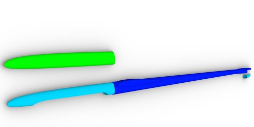
Once the wing design was completed, I was able to start working in CAD. Wings and tails are not a big deal here.
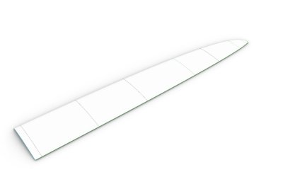
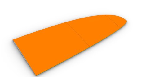
For me, the interesting part in CAD is always the fuselage. This is still the part that takes the most work for me. When it comes to the shape and dimensions of the fuselage, I draw on my experience with previous projects. The fuselage of the first Thor was comparable to the then very slim fuselage of the Freestyler3. A design by the Herrig brothers that really made history in F3f and F3b. But a lot has happened since then. The RC components have become smaller and more powerful and today (U)HM and IMS carbon fibers are more readily available and easier to get. So the fuselage cross-sections have been reduced over time. Extreme examples today are the Pitbull3, the Mojo and, above all, the Valkyrie. Here you can see the THOR and the Valkyrie in direct comparison:
It seems that Prandtl-D is not only discussed among German-speaking model builders...
Back to the Thor.2
Once the wing design was completed, I was able to start working in CAD. Wings and tails are not a big deal here.


For me, the interesting part in CAD is always the fuselage. This is still the part that takes the most work for me. When it comes to the shape and dimensions of the fuselage, I draw on my experience with previous projects. The fuselage of the first Thor was comparable to the then very slim fuselage of the Freestyler3. A design by the Herrig brothers that really made history in F3f and F3b. But a lot has happened since then. The RC components have become smaller and more powerful and today (U)HM and IMS carbon fibers are more readily available and easier to get. So the fuselage cross-sections have been reduced over time. Extreme examples today are the Pitbull3, the Mojo and, above all, the Valkyrie. Here you can see the THOR and the Valkyrie in direct comparison:
Martin Hepperle has done a nice analysis of the drag on an F3b model. Here you can see very nicely that the fuselage has a surprisingly high proportion of the total drag:
The fuselage of the THOR.2 has changed only slightly in its lever arms. The nose was only minimally shortened, the distance between the wing and the tail unit has shrunk by 10mm compared to the first Thor. In cross-section, the THOR.2 now fits between the two fuselages shown. So I tried to find a compromise here: Not too bulky to avoid an unnecessary increase in drag, but with enough space for trim lead, battery and 12mm servos (e.g. KST MS320).
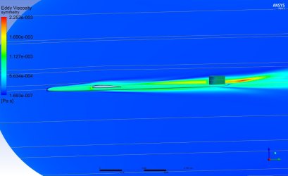
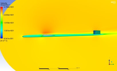
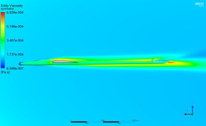
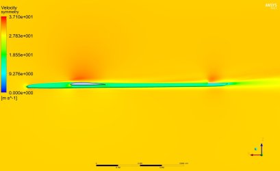
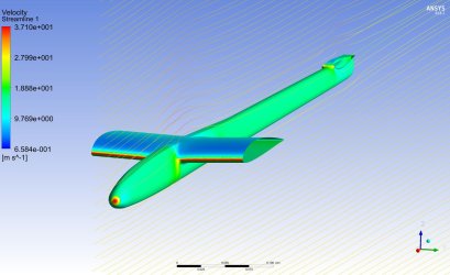
The cross-section shape resembles a triangle or, in the broadest sense, a droplet. There is a good reason for this: CDF simulations of various hulls (Vantage, Windcutter, a Pitbull-2 replica and, most recently, the Valkyrie) have shown that the cross-section of the hull plays a role in the drag of a model. You can imagine that a hull rarely faces the flow ideally. Most of the time it is approached from above or below, sometimes from the left or right. Depending on the angle of attack, the cross-sectional shapes now behave differently. With increasing angle of attack (e.g. in Turns), the resistance of rectangular hulls such as the Pitbull2 increases more than that of oval cross-sections (Windcutter). We found the smallest increase with triangular hulls, as used in the Freestyler series or my Vantage. The Valkyrie shape cut best, but this is certainly also due to the even smaller total surface area:
Doc J
Very Strong User
There is a trick to reducing the interference and induced drag.I'm amazed that fuselage drag adds up to that much especially since he broke out induced drag into its own section.
I'm curious if you have seen a study or have studied a low mounted wing on the same fuselage section compared to a top mount?
Doc.
Doc J
Very Strong User
"It seems that Prandtl-D is not only discussed among German-speaking model builders..." That's true. Nobody is doing anything new. But why not?
I'd advise "German-speaking model builders" to look more closely at Al Bowers and Red Jensen's work at NASA. It takes Prof Prandtl's 1933 paper to a completely different and now well-proven level.
In fact, the recent designs of German-speaking model builders seem to be almost a production line of similar models, or "Me Too's," as I call them.
The problem is that the model designs are based on computer predictions that are unreliable at best. The model does not fly in a bit/byte linear environment. But for most people, that is all that is available, and so they are believed as gospel.
But let's look: Does anyone really think that air flows over a wing in nice, straight lines, as we want it to?
The computer makes no accommodation whatsoever for a phenomenon as simple and well-known as a spanwise flow, which is not only important but absolutely critical for designing a fast wing. In a fast design, all of the influencing factors must be considered because, like water, air does what IT wants to do and not what WE want it to do.
For example, a computer-generated theoretical lift pattern, like computer-based aerofoil performance predictions, is an indication but can be very far from the most important objective, which is the actual dynamic lift performance of a model in flight.
When a model is flying, something different happens to it every second or less, and this is certainly not based on any computer prediction. Added to that are the almost constant control tweaks the pilot makes while flying. All have an influence.
I, too, use computer simulations and predictions, but I know very well that the computer, at best, will give you some idea but no certainty. Air is compressible - it has no linearity.
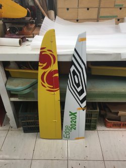
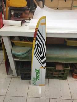
For reference, there are two photos below. The yellow Typhoon wing was designed by me 16 years ago using computer prediction—this is similar to wing shapes in use even now. I designed its successor, the Typhoon Toccata, last year using practical wind tunnel data—you can see quite a difference. As far as I know, this is the first wing made using BSLD theory adapted to a conventional (tailed) regime.
Of particular note is the planform, which is optimized to control the lift distribution and, therefore, the spanwise flow towards the tips. The wing 'cut off' tips are for vortex control, and the ailerons end well before the tip area to avoid unwanted disturbance.
In my 40 years of designing fixed-wing UAVs, I have discovered something: You need wind! Ask the Guys at NASA Ames or those who operate the wind tunnels at Boeing or Airbus. Those air tubes are fearsomely expensive to build and run. Why do they need them? Why not just fire up the old laptop?
Good luck with the model - I'm sure it will be a good and safe flyer.

Cheers,
Doc
I'd advise "German-speaking model builders" to look more closely at Al Bowers and Red Jensen's work at NASA. It takes Prof Prandtl's 1933 paper to a completely different and now well-proven level.
In fact, the recent designs of German-speaking model builders seem to be almost a production line of similar models, or "Me Too's," as I call them.
The problem is that the model designs are based on computer predictions that are unreliable at best. The model does not fly in a bit/byte linear environment. But for most people, that is all that is available, and so they are believed as gospel.
But let's look: Does anyone really think that air flows over a wing in nice, straight lines, as we want it to?
The computer makes no accommodation whatsoever for a phenomenon as simple and well-known as a spanwise flow, which is not only important but absolutely critical for designing a fast wing. In a fast design, all of the influencing factors must be considered because, like water, air does what IT wants to do and not what WE want it to do.
For example, a computer-generated theoretical lift pattern, like computer-based aerofoil performance predictions, is an indication but can be very far from the most important objective, which is the actual dynamic lift performance of a model in flight.
When a model is flying, something different happens to it every second or less, and this is certainly not based on any computer prediction. Added to that are the almost constant control tweaks the pilot makes while flying. All have an influence.
I, too, use computer simulations and predictions, but I know very well that the computer, at best, will give you some idea but no certainty. Air is compressible - it has no linearity.
For reference, there are two photos below. The yellow Typhoon wing was designed by me 16 years ago using computer prediction—this is similar to wing shapes in use even now. I designed its successor, the Typhoon Toccata, last year using practical wind tunnel data—you can see quite a difference. As far as I know, this is the first wing made using BSLD theory adapted to a conventional (tailed) regime.
Of particular note is the planform, which is optimized to control the lift distribution and, therefore, the spanwise flow towards the tips. The wing 'cut off' tips are for vortex control, and the ailerons end well before the tip area to avoid unwanted disturbance.


In my 40 years of designing fixed-wing UAVs, I have discovered something: You need wind!
Good luck with the model - I'm sure it will be a good and safe flyer.
Cheers,
Doc
Last edited:
vanquish
Active User
Yes, I was surprised by that too. The graphic shown with Martin Hepperle (MH-Airfoils) is already a few years old. The late Max Steidle, designer of many really excellent models (e.g. Shino F3f/b, Sensor F5J), did wind tunnel tests with the Shinto some time ago and was able to confirm MH's statements about the fuselage resistance, among other things. I don't know the exact results, but it led to Max also slimming down his fuselage designs for fast models.I'm amazed that fuselage drag adds up to that much especially since he broke out induced drag into its own section.
I'm curious if you have seen a study or have studied a low mounted wing on the same fuselage section compared to a top mount?
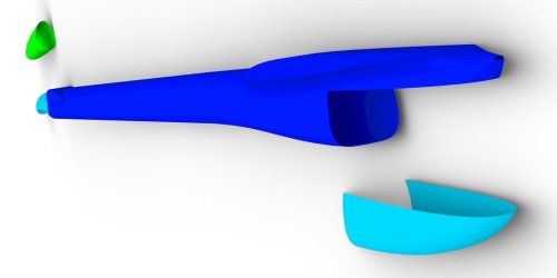
Well, CFD analyses are very compute-intensive. At the time, we had the opportunity to do this on a friend's university server. Nevertheless, the analyses ran between 18-30 hours per hull. So we could only do a limited number and used hulls of actual existing models so that we could compare the calculation results with our subjective perceptions. The screenshots of the CFD simulation shown above show the Vantage fuselage. Here, the wing does not extend beyond the fuselage. The same applies to the tail unit. Below I show the screenshots of the “Windcutter” fuselage. In this fuselage, the wing extends beyond the fuselage, and the tail is also offset slightly upwards. You can see quite well what happens here:
With increasing/decreasing angles of attack, however, this phenomenon decreases and the fuselage cross-section gains the upper hand.In the case of THOR.2, the wing and tail also extend beyond the fuselage. In the case of the wing, the reason for this is that the fuselage is then easier to grip for take-off. A good grip with a secure throw is more important to me here than a little less drag. With the tail unit, I accept this increase in drag if I gain a significant amount of length for the linkage levers and also get the tail unit itself out of the wing's downwash.
I would have found it very interesting to simulate the fuselage of the Avatar. Dirk Pflug has worked intensively on the fuselage/wing transition. Unfortunately, I don't have any CAD data for this and, in my opinion, a “replica” in CAD doesn't make sense without the exact profiling of the transition.
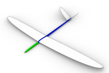
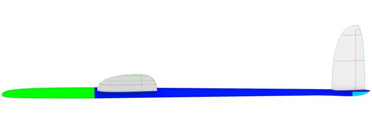
I can't really say much about the work in CAD, but just show the result:
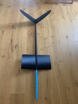
Just for fun, I 3D printed the fuselage, tail unit and a wing root for checking before I mailed the final data to TJIRC:
Kind regards,
Mario
