What's new
Aloft Forums

This is a sample guest message. Register a free account today to become a member! Once signed in, you'll be able to participate on this site by adding your own topics and posts, as well as connect with other members through your own private inbox!

DLG-BOW 110 - The Slope/DLG Wing

Wayne

Administrator
Staff member
Joined
Nov 29, 2017
Messages
7,856
Solutions
2
Reaction score
4,582
Location
Novato, CA USA
I'm excited to share this new kit with you all. This is a very good looking model, a well refined design and it is really an enjoyable and easy build. I'm going to show as much detail as possible here, so it might look like a tough build, but is is actually pretty darn easy.

Here is a link to the Assembly Notes, it is mostly a link to this build thread with some additional details. HERE.

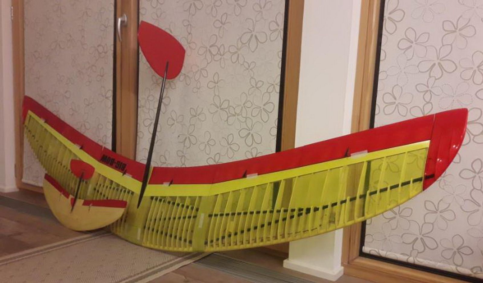
Ok first up a bit about the BOW series of wings. The BOW's are designed by a dedicated pair of crazy wing guys in Austria, David and Franz. They have refined these wings over many different designs and they range in size from 900mm to 2800mm spans.
picture-1600

Over the years they have really refined their craft and I have to say it shows!

Basic specs for the 110
Wingspan: 1100mm
Wing area: 19.1dm2
Length: approx. 526mm
The kit can be set up for the Discus launch for both left-handed and right-handed pilots. She is great as a thermal hunter or on the slope.

What we will be showing on this first build is our prototype, I failed to take photos of a couple of steps and there may be slight changes in the final kits. I must say it went together so nice! OK - Lets get started.

Get yourself a nice clean and flat build area. Roll out the plans and get started. I tried a couple of simple things on this build. I used a flat piece of wood and used some masking tape to put a nice clean sheet of cardboard down to the wood. This gives me a nice surface I can push pins into, this worked very well. I also like to cover the plans with something. In the past I used wax-paper, but this time I used some of our laminating film. Worked great! Think I used some 3 mil. CA glues does not stick to the shiny side of the film much at all. :)

Here I am test fitting the first couple of parts. Yep, looks good! (I love that leading edge shape.)
Bow110 build - 1.jpeg


Still checking parts/ This little center rib has a lot going on. Nice to see the laser has not issues with it.
Bow110 build - 2.jpeg


Building up the center box and test fitting the spar. Follow the plans for the details as there are several parts coming together. Once you have this box together you may want to test fit the tail tube. It should be a nice snug fit. Make sure you are using the correct 7mm OD tube, not the longer 8mm tube.
Bow110 build - 4.jpeg


Onto the wing tips. They are pretty darn simple, just fallow the drawings on the plans. If you plan to install the DLG post, now is the time to figure out what side you would like it on.
Bow110 build - 5.jpeg


Bow110 build - 7.jpeg


Time to mark the spars for cutting. Just lay them in position and mark your cut with some tape. I use a little arrow so I know what side to cut on. NOTE: When cutting carbon it is a good idea to protect yourself from the dust, it is not good stuff to inhale.
Bow110 build - 8.jpeg

Bow110 build - 9.jpeg

Bow110 build - 10.jpeg

And test fit it all into the center box:
Bow110 build - 11.jpeg
 
Last edited:

Wayne

Administrator
Staff member
Joined
Nov 29, 2017
Messages
7,856
Solutions
2
Reaction score
4,582
Location
Novato, CA USA
And we just keep going. Here I am just test fitting the wing tips to make sure everything is right. Do not glue these in place yet!
Bow110 build - 12.jpeg


We don't glue all of that as we need to be able to slide these ribs onto the spars. There is only one way to do this, slide them onto the center spar first, then slide main spar into the ribs.
Bow110 build - 13.jpeg


Now we keep sliding on ribs and the wing tips and then we can fit the leading edges. Take your time with the leading edges, slowly work them into place little by little. Due to the shape they may look like they are the wrong size, but as they work into place, they are a perfect fit. Just go back and forth and slowly seat them onto each rib.
Bow110 build - 14.jpeg


When you are happy with the fit, you are ready to glue all of the joints. I use a number of push pins to hold things in place, and a little weight to make sure it all stays flat on the board.
Bow110 build - 15.jpeg


At this point I am missing some photos. But we will be adding the leading edge onto the front of the leading edge wood into this space:
Bow110 build - 17.jpeg

Here are some pictures from Franz's build. You will need to file in a little groove at the wing tip. (I used a Dremel with a cutoff wheel for this.)
dlg-bow11.jpeg


In this photo you can see the white leading edge installed, and the wrapping of the spars with some thread and thin CA.
dlg-bow12.jpeg


And installing the tailboom. In this photo it is a one part boom, on new kits it is a removable 2 part unit for quick changing and easy transport.
dlg-bow13.jpeg
 

Wayne

Administrator
Staff member
Joined
Nov 29, 2017
Messages
7,856
Solutions
2
Reaction score
4,582
Location
Novato, CA USA
Onto the center sheeting. We will add a little lip to the inside:
Bow110 build - 18.jpeg

Bow110 build - 19.jpeg

And here again I failed to take some pictures. But you now want to install your servo wires and route them from the servos through the ribs and into the radio box. And then we can test fit our forward sheeting, note the routing of the servo wires under the spar and into the radio compartment.
Bow110 build - 20.jpeg


All should be fitting well. Starting at the leading edge carefully align and glue the sheeting to the leading edge. Some CA and kicker is handy for this step. Once cured to the leading edge I ran some medium CA to the rib tops and rolled the sheeting back. A little kicker and should be set in place. Adding the rear section is easy, do some test fitting to get a nice tight fit with the tail tube, then glue into place.
Bow110 build - 22.jpeg
 

Wayne

Administrator
Staff member
Joined
Nov 29, 2017
Messages
7,856
Solutions
2
Reaction score
4,582
Location
Novato, CA USA
OK, let's take a close look at the servo install. It should look something like this:
index.php

It is recommended to use a high quality servo brand. Here we are using KST X08H. They screw right into place. I used a small drill to start the screws and position the servo. You will need to trim your servo arm so it will fit under the top of the rib. We do not want it rubbing on our covering. Also note the small length of music wire with a Z bend. Here is another shot showing a bit of detail:
Bow110 build - 24.jpeg

Why not a full length of wire for the linkage? Well, we want to cover over this with our film, so after covering we can cut our slit and slide a tube onto the music wire. Did you notice the slight arc in the wire? I like to do this to add some friction to the tube.
Bow110 build - 25.jpeg

This side is a bit cleaner:
Bow110 build - 26.jpeg


I also forgot to take pictures of the sanding and fitting of the trailing edge parts. You may have noticed them installed in the photos of the tail tube. My bad. Just check the plans and sand to shape. The hinge bevel for the elevons will be visible on the top, and the hinge will be on the bottom. This is important.

Time to look things over and do some touch up sanding. Get everything smooth and ready to cover.
Bow110 build - 31.jpeg


I started on the bottom:
Bow110 build - 32.jpeg

Then moved over to the top, pretty much just sealing down the edges, and making sure I have good overlap so nothing let's go when I shrink the middle tight.
Bow110 build - 34.jpeg


I like to use a heat gun for the center shrinking.
Bow110 build - 35.jpeg


And here is that servo all covered up, and ready to cut a small slit to glue the tube for the linkage. Sweet!
Bow110 build - 37.jpeg


Basically done. Just need to install the control horns and linkage, set the throws and CG.
Bow110 build - 40.jpeg


Did you spot the missed steps? LOL I totally failed to take photos of the vertical fin build. It is dirt simple. Glue the parts together as shown on the plans, sand the leading edge round and trailing edge sharp. Cut a slit in the carbon tube and all should slide nicely. Glue the fin into the tube. Some sanding may be needed on the carbon tubes to have a nice firm fit. A bit of tape can be used to secure the tail to the fixed tube.

There are some other steps I failed to document. I'll add details to this as needed. Some thing I know I missed are the ballast chambers, final radio install, control horns and linkage, installing the servo mounts during the rib installation, installing the throwing peg and probably a few others.

The kits will come with 2 tail options. The DLG tail is shown above and there is also a slope version that does not have the lower section and a little different shape.

I hope you have enjoyed following along, and we look forward to seeing your builds!
 

Attachments

  • Bow110 build - 23.jpeg
    Bow110 build - 23.jpeg
    310.8 KB · Views: 479

Wayne

Administrator
Staff member
Joined
Nov 29, 2017
Messages
7,856
Solutions
2
Reaction score
4,582
Location
Novato, CA USA
An additional resource for building and discussion can be found here in a German forum:
 

thenated0g

Very Strong User
Joined
Dec 5, 2017
Messages
2,790
Reaction score
2,592
Location
Lakeport, ca
Great build, love how these look. Neat seeing all the different types of inset wood for different things.

So are you guys going to be making these now?
Ill go back and look but how are they keeping that vertical....vertical, if its removable? Tape around the tube?
 

Wayne

Administrator
Staff member
Joined
Nov 29, 2017
Messages
7,856
Solutions
2
Reaction score
4,582
Location
Novato, CA USA
Yes, we will have them available pretty soon. This build was a test build to make sure everything fits well and ordering in the custom bits needed. All stock is here now and ready to jump into production. Still need to work out packaging, etc, but will be cutting kits as soon as we get caught up with some other laser projects currently in progress. I think we will have them up on the site next week.
 

Wayne

Administrator
Staff member
Joined
Nov 29, 2017
Messages
7,856
Solutions
2
Reaction score
4,582
Location
Novato, CA USA
Sorry, I forgot to answer the question about the vertical. There are 2 tubes, a short length that gets glued into the plywood center section, and the longer removable tube that is a friction fit for the tail. I chucked up the smaller tube in a drill and lightly sanded for a nice wedge fit. Works very well. I can pick up the entire plane by the boom. :)
 

Hawaii Sloper

Very Strong User
Joined
Jun 26, 2022
Messages
532
Reaction score
598
Location
Kona Hawaii
Sorry, I forgot to answer the question about the vertical. There are 2 tubes, a short length that gets glued into the plywood center section, and the longer removable tube that is a friction fit for the tail. I chucked up the smaller tube in a drill and lightly sanded for a nice wedge fit. Works very well. I can pick up the entire plane by the boom. :)
Like a 2 piece fishing rod? love this design. Was it designed with Winghelper? How did the oval cuts for the angled carbon tube spar work out? did they need individual fitting?
 

Wayne

Administrator
Staff member
Joined
Nov 29, 2017
Messages
7,856
Solutions
2
Reaction score
4,582
Location
Novato, CA USA
No, this plane was designed in Austria and I think it was all drawn in a normal CAD package. Yes, it has ovals and yes they fit very well. I do not recall any custom fitting except a little for the leading edge on the wing tips, and sanding the trailing edge to shape. The fitment is great!
 

Wayne

Administrator
Staff member
Joined
Nov 29, 2017
Messages
7,856
Solutions
2
Reaction score
4,582
Location
Novato, CA USA
Should have the first 10 kits ready next week. ๐Ÿ˜Ž

Melted some woods metal into the nose tonight. First time I have used that with a wood structure. No issues! I used a sheet of paper rolled up into a funnel to help direct it into the very nose of the BOW. At one point some melted metal got onto my shrink film, it didn't hurt the film at all!

We used a little butane torch to melt it into my paper funnel. Love this stuff! Hard to get a picture, but:
woods metal - 1.jpeg


No need to cut open the ballast bay doors. Just let the liquid metal flow past the carbon tubes into the nose of the glider.

This prototype is probably on the heavy side as we did not attempt to select good wood for the build. Just the opposite, we selected some junky wood we did not want to send to customers. The wing tips on this one might as well be made of pine. LOL
 
Top