Robert asked me to post up his very detailed Slow Stick build as he was having some issues getting it posted. He should chime in here.
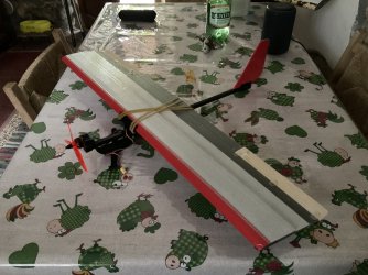
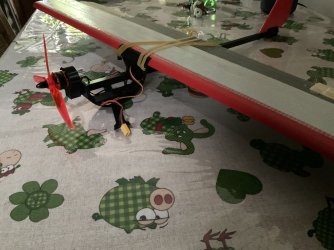
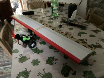
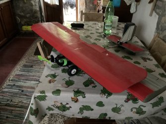
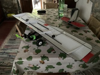
The attached photo shows my Slow Stick that weighs 16.0 ounces. This is at the very low end of the GWS recommended weight range. It includes a 2.6 oz 1300 mAh 2S LiPo battery, a pair of 3 inch 20 gram wheels, a redesigned main landing gear and a tail wheel. I fly off of grass so I wanted the wider diameter 3 inch wheels along with a substantially stronger landing gear.
The landing gear design incorporates a adjustable rubber band. Changing the tension allows you the user to vary the gear stiffness / flexibility to suit your specific needs (see photo). Since this is the most significant modification and requires special soldering and bending expertise, it will be discussed in more detail than the other modifications. These other modifications were made primarily for simplicity, to save some weight and for improving appearance. A list of the necessary build materials and equipment required to make these modifications are presented at the end of this article.

Wing Build
To save 9 grams of weight the fiberglass leading edge and trailing edge rods were replaced with 3 mm carbon fiber tubes and bamboo skewers respectively. The carbon fiber tubes also increased wing stiffness. The two carbon rods (leading edge) should be the length of the long fiberglass rods. The two trailing edge skewers should be the length of the short fiberglass rods. Sort through your bag of skewers and select two that are straight and the correct diameter. Start by using epoxy to secure the carbon tubes and skewers into the aluminum joiners. To ensure the specified dihedral angle of 10 degrees is obtained do the following: Hold one of the carbon fiber rods flat on the bench and measure the height of the tip of the other carbon rod above the bench. It should be 3.35 inches. If not bend the aluminum joiner. Do the same with the skewer assembly except it should be 1.54 inches high. Let the leading and trailing edge assemblies dry over night. When dry lay each flat on the bench and check to be sure that the two assemblies are both at the same angle. If they are not bend the aluminum joiner. Complete by taking a Sharpie and mark a narrow line at the center of each aluminum joiner. Next take an 1/8 inch rat-tail file and cut a 1/16 inch deep channel along the wing leading edge and trailing edge. This sounds hard to do but you will find it is quite easy to do and saves assembly time. Use the tapered portion of the file to cut about a 1/32 inch channel that is centered between the two skins. Don’t worry to much about depth variations. Just concentrate on keeping the channel centered. Now hold the file between your thumb and center finger. Place the file in the channel and slide the file fore and aft to cut the channel to the desired depth.
The leading and trailing edge assemblies can now be attached to the wing.
Place the wing vertical on your bench with the trailing edge flat on the face of the table. Place a couple of quart paint cans on each side of the center section to hold the wing in place. Trial fit the leading edge with the mark at the center line of the wing. If necessary deepen the channel where the aluminum joiner attaches to the wing. Use a tooth pick to place a small amount of epoxy to attach aluminum joiner. To save weight use E60000 along the rest of the leading edge channel. To keep the leading edge in place and centered use several 3 inch long pieces of clean release tape aligned perpendicular to the leading edge. Next reposition the wing on the bench so that the trailing edge is up and the leading edge is flat on the bench. Follow the same procedure on the trailing edge.
The clear plastic center section was then attached with epoxy. This was both ugly and heavy. Not a good combination. If you have other glue recommendations they would be appreciated. A black Sharpie was used to color the outline of the ailerons, skewers and the aluminum center joiners. Don’t color prior to gluing or you will not get a good glue joint. Mark a black CG line 4.125 inches back from the leading edge. The model flew best using this CG position. Make a CG holding jig from the GWS flashing (see first photo) as it will make balancing the model much easier.
Horizontal Tail and Rudder
Built to GWS plan except a spacer gage was used to better align and keep the hinge line straight and equally spaced. The gage was made by cutting a long narrow strip of material from a 0.020 inch thick piece of cardboard . Lay the tail and rudder on your bench and use some weights to hold the four parts in place. I found that a couple of socks filled with spare coins and sealed with a plastic tie wrap makes excellent weights. They won’t damage the foam. Next use the gage to establish a consistent hinge gap of 0.020 inches and lay down the first strip of wing tape. Per the GWS instructions fold the control surfaces over one another. But then place the gage between the two surfaces close to the hinge line prior to taping the final two edges. This will provide a stronger and more flexible hinge.
The attached photo shows my Slow Stick that weighs 16.0 ounces. This is at the very low end of the GWS recommended weight range. It includes a 2.6 oz 1300 mAh 2S LiPo battery, a pair of 3 inch 20 gram wheels, a redesigned main landing gear and a tail wheel. I fly off of grass so I wanted the wider diameter 3 inch wheels along with a substantially stronger landing gear.
The landing gear design incorporates a adjustable rubber band. Changing the tension allows you the user to vary the gear stiffness / flexibility to suit your specific needs (see photo). Since this is the most significant modification and requires special soldering and bending expertise, it will be discussed in more detail than the other modifications. These other modifications were made primarily for simplicity, to save some weight and for improving appearance. A list of the necessary build materials and equipment required to make these modifications are presented at the end of this article.
Wing Build
To save 9 grams of weight the fiberglass leading edge and trailing edge rods were replaced with 3 mm carbon fiber tubes and bamboo skewers respectively. The carbon fiber tubes also increased wing stiffness. The two carbon rods (leading edge) should be the length of the long fiberglass rods. The two trailing edge skewers should be the length of the short fiberglass rods. Sort through your bag of skewers and select two that are straight and the correct diameter. Start by using epoxy to secure the carbon tubes and skewers into the aluminum joiners. To ensure the specified dihedral angle of 10 degrees is obtained do the following: Hold one of the carbon fiber rods flat on the bench and measure the height of the tip of the other carbon rod above the bench. It should be 3.35 inches. If not bend the aluminum joiner. Do the same with the skewer assembly except it should be 1.54 inches high. Let the leading and trailing edge assemblies dry over night. When dry lay each flat on the bench and check to be sure that the two assemblies are both at the same angle. If they are not bend the aluminum joiner. Complete by taking a Sharpie and mark a narrow line at the center of each aluminum joiner. Next take an 1/8 inch rat-tail file and cut a 1/16 inch deep channel along the wing leading edge and trailing edge. This sounds hard to do but you will find it is quite easy to do and saves assembly time. Use the tapered portion of the file to cut about a 1/32 inch channel that is centered between the two skins. Don’t worry to much about depth variations. Just concentrate on keeping the channel centered. Now hold the file between your thumb and center finger. Place the file in the channel and slide the file fore and aft to cut the channel to the desired depth.
The leading and trailing edge assemblies can now be attached to the wing.
Place the wing vertical on your bench with the trailing edge flat on the face of the table. Place a couple of quart paint cans on each side of the center section to hold the wing in place. Trial fit the leading edge with the mark at the center line of the wing. If necessary deepen the channel where the aluminum joiner attaches to the wing. Use a tooth pick to place a small amount of epoxy to attach aluminum joiner. To save weight use E60000 along the rest of the leading edge channel. To keep the leading edge in place and centered use several 3 inch long pieces of clean release tape aligned perpendicular to the leading edge. Next reposition the wing on the bench so that the trailing edge is up and the leading edge is flat on the bench. Follow the same procedure on the trailing edge.
The clear plastic center section was then attached with epoxy. This was both ugly and heavy. Not a good combination. If you have other glue recommendations they would be appreciated. A black Sharpie was used to color the outline of the ailerons, skewers and the aluminum center joiners. Don’t color prior to gluing or you will not get a good glue joint. Mark a black CG line 4.125 inches back from the leading edge. The model flew best using this CG position. Make a CG holding jig from the GWS flashing (see first photo) as it will make balancing the model much easier.
Horizontal Tail and Rudder
Built to GWS plan except a spacer gage was used to better align and keep the hinge line straight and equally spaced. The gage was made by cutting a long narrow strip of material from a 0.020 inch thick piece of cardboard . Lay the tail and rudder on your bench and use some weights to hold the four parts in place. I found that a couple of socks filled with spare coins and sealed with a plastic tie wrap makes excellent weights. They won’t damage the foam. Next use the gage to establish a consistent hinge gap of 0.020 inches and lay down the first strip of wing tape. Per the GWS instructions fold the control surfaces over one another. But then place the gage between the two surfaces close to the hinge line prior to taping the final two edges. This will provide a stronger and more flexible hinge.
Attachments


Last edited:
")