What's new
Aloft Forums

Welcome to Aloft Forums. Register a free account today to become a member! Once signed in, you'll be able to participate on this site by adding your own topics and posts, as well as connect with other members through your own private inbox!

Aeroic Aresti 108 build

Motowncali

Active User
Let me start with... This Thing is a BEAST!
The plan is to put the servos in the tail. I also would like 2” of rudder each way for beautiful hammer heads...
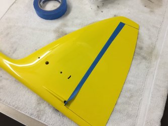
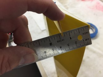
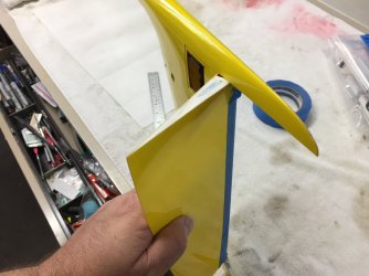
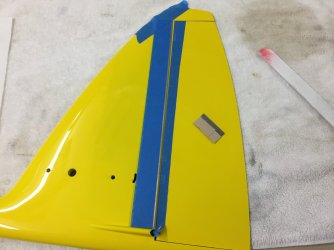
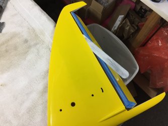
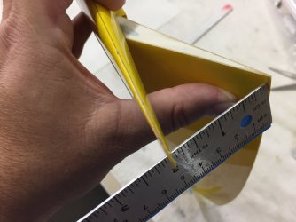
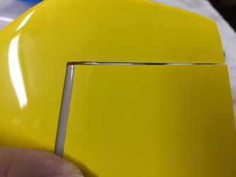
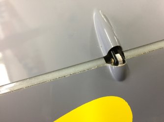
So, first thing that needs to be done is open up the gap slightly for the rudder. The swiper is smooth, but because of the shape and thickness, the rudder will have less effect when deflected opposite the hinge line, 1/2” of the rudder is now inside the post... carefully taped my ruler in place and removed an additional 1/8”, got a 1/2” more easy throw instead of fighting to move it... Yes, that is a 12” ruler on the rudder hinge line! Didn’t I say this thing is huge?!?
The next thing I noticed was the because of the taper of the vertical fin, the rudder was also offsetting vertically and rubbing at the top. A little careful sanding and I was able to get even freer movement. And you cant hardly tell the at the top gap is 2mm wide instead of 1mm.
 

Attachments

  • 4F111DAB-598E-439F-BD1B-15FFCD2FFFFA.jpeg
    4F111DAB-598E-439F-BD1B-15FFCD2FFFFA.jpeg
    215.1 KB · Views: 342
  • 1A3C3617-BB28-432A-8E98-D0F4AF8C7037.jpeg
    1A3C3617-BB28-432A-8E98-D0F4AF8C7037.jpeg
    173.4 KB · Views: 336
  • 0309E1C1-90E5-4F8F-A99B-B106C1EF4969.jpeg
    0309E1C1-90E5-4F8F-A99B-B106C1EF4969.jpeg
    195.2 KB · Views: 305
  • 6EEDF4F2-6D33-4E48-89C2-EE3C2E47D3EA.jpeg
    6EEDF4F2-6D33-4E48-89C2-EE3C2E47D3EA.jpeg
    210.6 KB · Views: 309
  • 758877E3-6D19-4C98-9DD8-0C6EBDCEAF50.jpeg
    758877E3-6D19-4C98-9DD8-0C6EBDCEAF50.jpeg
    223.6 KB · Views: 292
  • 480DAEF0-6ABC-4977-A84D-ECFAFC6BA1CD.jpeg
    480DAEF0-6ABC-4977-A84D-ECFAFC6BA1CD.jpeg
    189.2 KB · Views: 287
  • B6B14238-8114-4DE9-8CC7-81B19EFF91A9.jpeg
    B6B14238-8114-4DE9-8CC7-81B19EFF91A9.jpeg
    102.1 KB · Views: 288
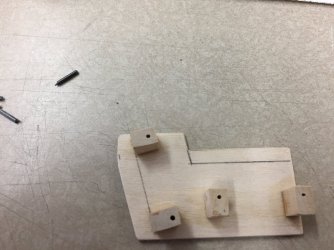
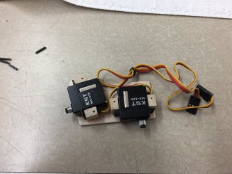
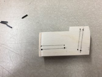
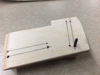
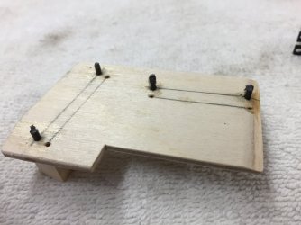
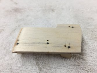
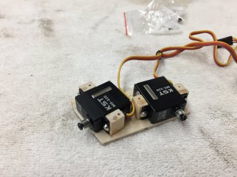
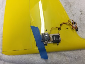
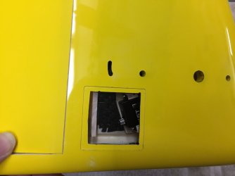
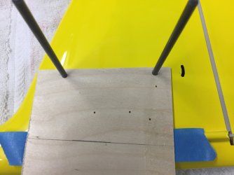
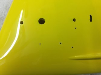
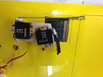
Servo Mount is 1/8”, a little trimming hear, a bit of trimming there, carefully cut some blocks, tack them in place and two and half hours later, the tail servos slide in on a beautiful tray. As done with the previous Aresti build and the Gremlin build, the elevator servo is forward at a slight angle for the top hinged stab. With as tight as this is, I am going to make a template using the anti rotation pins as a guide and will use four 2-56 flat head screws threw the otherside of the fuse to hold the servo tray in place. The screws will thread right into the four servo mounting blocks. There is already a layer of carbon on that side of the fuse, should pull up nice and tight and be completely smooth.
Rudder control rod will cross the fuse at a slight angle much like your aileron linkages.
 

Attachments

  • C46006B0-E573-4F87-AAC9-12DB2924428F.jpeg
    C46006B0-E573-4F87-AAC9-12DB2924428F.jpeg
    278.9 KB · Views: 308
  • 35515667-FAC6-41C9-8A85-3ED64AE5E61A.jpeg
    35515667-FAC6-41C9-8A85-3ED64AE5E61A.jpeg
    287.9 KB · Views: 284
  • 911B6482-5296-4624-A3F7-C2EC2571D087.jpeg
    911B6482-5296-4624-A3F7-C2EC2571D087.jpeg
    246.7 KB · Views: 296
  • E9831970-0DB3-4C03-91A7-1ECC737315ED.jpeg
    E9831970-0DB3-4C03-91A7-1ECC737315ED.jpeg
    170 KB · Views: 291
  • C3B3EE2C-9BF8-4379-8CAE-AD9C52245264.jpeg
    C3B3EE2C-9BF8-4379-8CAE-AD9C52245264.jpeg
    189.8 KB · Views: 269
  • E3043954-B3F9-4A6D-82F8-6ECA8B87428A.jpeg
    E3043954-B3F9-4A6D-82F8-6ECA8B87428A.jpeg
    179.3 KB · Views: 272
  • 4B2521FC-C803-47EB-B9D3-E15028C58CDE.jpeg
    4B2521FC-C803-47EB-B9D3-E15028C58CDE.jpeg
    229.4 KB · Views: 290
  • 1A75F85F-C67F-4CEB-874F-16EA90DBE4F0.jpeg
    1A75F85F-C67F-4CEB-874F-16EA90DBE4F0.jpeg
    184.5 KB · Views: 306
  • 8D22F1C8-81F6-460F-B196-D32D569C8372.jpeg
    8D22F1C8-81F6-460F-B196-D32D569C8372.jpeg
    111.1 KB · Views: 309
I see where you and I think much the same. In my sport ships I love all the rudder I can get. I also like the fly by wire set up (servos in the rear). I also like your ganged servo tray in the back.

Well done!

All the ebst,
Konrad
 
Slick idea for sure. Do you have a pic what it will look like on the side that you bolt down the tray with the screws installed? Just curious.
 
Like the carbon pins to help keep those blocks in place. :) Good idea, I remember popped a hard wood block off once on a so-so landing. That pin would have avoided that issue.
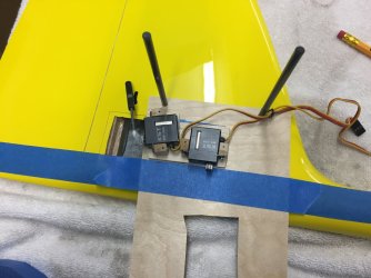
 
It’s been a little while since I worked on this, so back out it came. Happy to say linkages to the elevator and rudder are done, servo extensions made.
Used a piece of 1/32 ply to make a hole template to align the servos and drill the holes in the other side of the fuse. Flat head 2-56 screws are on the way so that I can countersink and mount one last time. Will put up a pic when done. Linkages are tight and throws look good. Wouldn’t mind having a little more throw in the rudder, but the fuse is only so wide.
 

Attachments

  • 77D794C1-AA6A-4AE5-84C6-510E17C9BBED.jpeg
    77D794C1-AA6A-4AE5-84C6-510E17C9BBED.jpeg
    243.7 KB · Views: 270
  • F3BF8A5C-12BE-4419-B893-BDDD74913615.jpeg
    F3BF8A5C-12BE-4419-B893-BDDD74913615.jpeg
    178.7 KB · Views: 278
  • 9530C81C-D64C-47D8-B574-D48DB251D613.jpeg
    9530C81C-D64C-47D8-B574-D48DB251D613.jpeg
    96.2 KB · Views: 274
  • 7A36192D-CC9D-4C10-85D0-31C0B07E7D80.jpeg
    7A36192D-CC9D-4C10-85D0-31C0B07E7D80.jpeg
    156.6 KB · Views: 295
Looks great Mo!
Maybe if you use a shorter servo arm? In the D60 build you have to drill another hole so close to the servo gear it is crazy. Either that or you can use a MKS servo and use one of Spencer's short servo arms. Just a thought for the future? Plus having that ply in there I sure takes up some room as well.
Cant wait to see her fly! :D
Had to drill the dimples in the factory arms to get the resolution where I wanted it on many builds. But on this, want to go the other way, longer arm. The tail is actually quite wide at 20mm
 
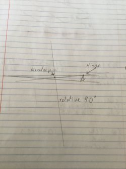
Why the slant of the elevator servo? I notice that it looks to be not tangent to the arch. I've seen this with more than one installation.

All the best,
Konrad
 
Why the slant of the elevator servo? I notice that it looks to be not tangent to the arch. I've seen this with more than one installation.
All the best,
Konrad

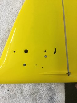
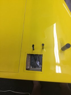
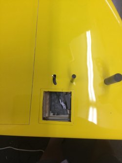
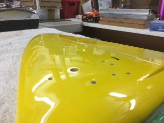
I may be the only one doing this, not sure. But with the top skin being the hinge and the wire that connects the elevator halves being below the hinge line, moving the servo forward and angling the rod back, gives better down resolution.
You can also see it in the shape of the arc cut out in the fin. The rod moves forward in the down travel and almost straight up in up travel.
 

Attachments

  • image.jpg
    image.jpg
    199.9 KB · Views: 269
  • image.jpg
    image.jpg
    193.7 KB · Views: 278
  • image.jpg
    image.jpg
    120.9 KB · Views: 274
  • image.jpg
    image.jpg
    118.8 KB · Views: 270
Thank you!
So you are tangent. I was looking at the chord line. Not as you correctly mentioned the hinge point. The hinge is what defines the arch.

Again thank you.

All the best,
Konrad
 
Last edited:
So you are tangent.

Nope, he is Mo.

You might be happy to know what Hammond is working on a molded tray for the tail on one of his new models. Should be interesting and much easier for future installs. :)
 
Aresti 108. It has been a fun process getting both servos in the tail and totally worth it! Came out very clean and the surface centering is great! Flat head screws showed up. Damn that’s clean if I don’t say so!
 

Attachments

  • 57C3C7C2-35CD-40E1-A632-041209A8A46C.jpeg
    57C3C7C2-35CD-40E1-A632-041209A8A46C.jpeg
    172.7 KB · Views: 292
  • DC777DE3-E44E-41CE-828F-956CBE7138E1.jpeg
    DC777DE3-E44E-41CE-828F-956CBE7138E1.jpeg
    241.7 KB · Views: 289
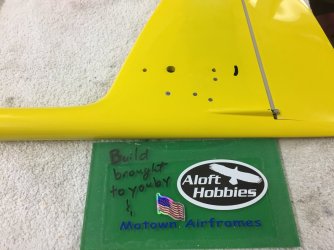
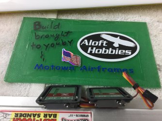
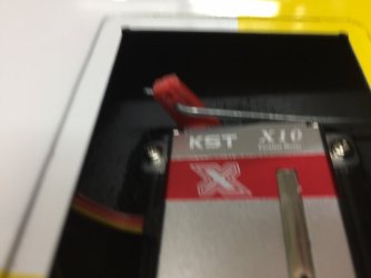
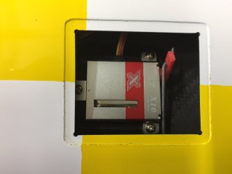
Just getting going on the wings, drilled and mounted the KST X10’s to the frames and was very surprised that the screws came out the other side. If these had been in the wing, they would have come through the skin...
 

Attachments

  • 2D158C4D-3392-4B6D-8731-E963557716F1.jpeg
    2D158C4D-3392-4B6D-8731-E963557716F1.jpeg
    280.9 KB · Views: 291
FYI; there may be are other traps awaiting.
 
Installing the frames was too easy on this plane. Linkages were straight and the MPJet clevises work flawlessly.

Since there are no servos in the nose of the plane, I added a 1/32 ply top to the servo tray. This made mounting the receiver and battery much cleaner.
8562949D-F6DC-4061-8172-DC54568ADE27.jpeg
7295294F-ACC6-4A1E-8D64-88BA78692ED7.jpeg
64847380-6123-4BA7-AA5D-2AA7FC1E3505.jpeg
A4E16F5C-0476-4353-B2A0-22515D536A06.jpeg
62370A1E-5726-4A89-970F-E974BD52FC62.jpeg
 
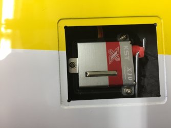
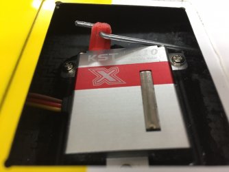
Some quick photos of the servos installed. Very straight forward. Didn’t even need to bend the pushrods, they are straight shots to the horns. Aileron horns slightly offset trying to get more up than down mechanically, still requires a little differential in the tx to get it where I want to start.

Took 20 ounces in the nose to achieve a 140mm CG. Will add another 1.5 ounces to maiden at 130mm and see where it goes from there.
 

Attachments

  • 12B9CBCD-7458-45F0-8C4D-704A4E167265.jpeg
    12B9CBCD-7458-45F0-8C4D-704A4E167265.jpeg
    136.8 KB · Views: 255
  • EF7F9762-4D29-4965-9760-AED318DC69D5.jpeg
    EF7F9762-4D29-4965-9760-AED318DC69D5.jpeg
    148.3 KB · Views: 264
  • BFC5AB94-4B5D-45AF-8B4C-B4B6F1941933.jpeg
    BFC5AB94-4B5D-45AF-8B4C-B4B6F1941933.jpeg
    111.6 KB · Views: 266
  • 4988F8C8-6CD0-4154-9DFA-B65C059E0619.jpeg
    4988F8C8-6CD0-4154-9DFA-B65C059E0619.jpeg
    129.4 KB · Views: 267
  • 4E216DB3-492B-4175-BF3E-408AF623346C.jpeg
    4E216DB3-492B-4175-BF3E-408AF623346C.jpeg
    130.1 KB · Views: 262
Back
Top