Hi Konrad - nice to talk to you.
OK, first I would like to point out that in fact the Samsara is really a very good plane as is,

and its only my rough flying and the avilalblity of other parts I have for my own model line that makes me think about changing anything.
Here are some answers to your comments below:
-------
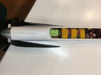
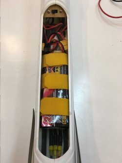
Yikes, all that wiring gave me a fright.
------
(JH) Hahaha - I made up over 100 wiring harnesses for my planes.
I’ve often wondered about the effectiveness of the cover’s hood. I know on racers we try to not have any of the control system in the slipstream. But if the arms, rods, and horns are in the airstream does the hood actually help cut down on drag? Or are the hoods just to help keep the weeds from damaging the controls?
-------
(JH) If the fairing is on the bottom of the wing, then a
good one is quite effective as the bottom part is often operating in actual laminar flow - in this case anything you can do to remove or reduce bumps etc is good.
On the top of the wing its a different story. Even fast F3f racer the upper surface of the wing is never actually laminar. Its not until we get to the middle DS speeds that it can happen. Normally the boundary later will separate at about 40% to 60% on the top surface, so any fairing you have after that is not helping at all.
------
On my wing front pin mounts I try to add roll off ramps. I find that vertical standoffs often keep the wing in place allowing the wing to leverage (pry) the fuselage apart.
As it looks like you cut into the sheeting can you tell us what you anchored the front mount to. And as I see you added a spreader plate to the rear bolt hole, I may do the same. As I’ll need to have the covering iron out to get full travel from of the flaps.
------
(JH) I just made box and cut it completely down into the wing structure and glassed and epoxied it in.
-----
Lets be brutally honest, we will have to replace flap servos. To that end I too like to use servo mounting plates. Aloft carries these.
https://alofthobbies.com/servo-tray-for-mks-ds-6125-glider.html
-----
(JH) If you look at the pictures you will see I have already done this. I used my own servo trays but these are not commercially available - Waynes trays are great.
-----
But as they often cost a large fraction of the price of a servo I only use them on flap servos. I still glue in most of my servos with a preinstalled cut wire (Dental floss).
-----
(JH) Well as I said, I do have parts available so I use them.
All the best,
Konrad